Voltage-gated Channel Structure
The activities of voltage-gated channels determine the responses of excitable tissues throughout the body.
This tutorial focuses on describing the structure and function of various membrane channels involved in
the behavior of these tissues. This tutorial is 'required reading' for the following tutorials on the cardiac pacemaker
and heart contractility.
Structure
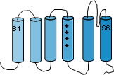 Channels are composed of large membrane-embedded proteins. These long proteins make six passes through the cell
membrane coiling into alpha helices as they do so. In these tutorials these alpha helices are represented as solid
cylinders. The helices are referred to as the 'transmembrane domain' while the sections beyond the membrane are called
'linkers'. The helices are numbered S1 through S6. The illustration to the left shows
the protein in a stretched-out arrangement. The S4 helix is unique because it has a series of positive charges along
its length. Another unique feature is that the linker between S5 and S6, that is at the outer membrane surface, forms
a hairpin-shaped loop that hangs down between S5 and S6.
Channels are composed of large membrane-embedded proteins. These long proteins make six passes through the cell
membrane coiling into alpha helices as they do so. In these tutorials these alpha helices are represented as solid
cylinders. The helices are referred to as the 'transmembrane domain' while the sections beyond the membrane are called
'linkers'. The helices are numbered S1 through S6. The illustration to the left shows
the protein in a stretched-out arrangement. The S4 helix is unique because it has a series of positive charges along
its length. Another unique feature is that the linker between S5 and S6, that is at the outer membrane surface, forms
a hairpin-shaped loop that hangs down between S5 and S6.
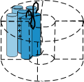 Voltage-gated channels are composed of four such proteins arranged in a circle so that there is a 'pore' between them as shown
to the right. Notice that the S5-S6 linker, also called the P loop, hangs into the pore. This loop is part of the 'selectivity
filter' at the outer mouth of the pore; there are four such loops in all. The S4 helix is called the 'sensor' and, depending
on the charges at the inner and outer membrane surfaces, will moves back and forth within the membrane.
Voltage-gated channels are composed of four such proteins arranged in a circle so that there is a 'pore' between them as shown
to the right. Notice that the S5-S6 linker, also called the P loop, hangs into the pore. This loop is part of the 'selectivity
filter' at the outer mouth of the pore; there are four such loops in all. The S4 helix is called the 'sensor' and, depending
on the charges at the inner and outer membrane surfaces, will moves back and forth within the membrane.
Gates
There are usually two gates associated with these channels. One is called the 'activation gate' and, when it opens (activation),
ions can flow through the pore within the channel. The other is called the 'inactivation gate' and, when it closes (inactivation),
the pore is closed off stopping the flow of ions. The flow of ions will also stop if the activation gate closes (deactivation) before
the inactivation gate closes.
Activation Gate
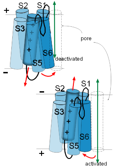 The illustration to
the left shows the S6 helix of one of the proteins facing the pore that is at the right. Depending on the
particular channel under discussion, these helices can move in various ways to either open or close the pore they are
facing. All four S6 helices form the activation gate. 'Activation' occurs when these helices, of all four proteins, move so as
to open the pore and 'deactivation' is when they are positioned so as to obstruct the pore.
The illustrations at the left show how the movements of activation gate helices might be visualized.
The illustration to
the left shows the S6 helix of one of the proteins facing the pore that is at the right. Depending on the
particular channel under discussion, these helices can move in various ways to either open or close the pore they are
facing. All four S6 helices form the activation gate. 'Activation' occurs when these helices, of all four proteins, move so as
to open the pore and 'deactivation' is when they are positioned so as to obstruct the pore.
The illustrations at the left show how the movements of activation gate helices might be visualized.
These movements of the activation gate helices occur because of the movement of the associated S4 helix.
Being positively charged, an S4 helix is attracted toward the negative inner surface of the membrane. However, depending on the
channel being discussed, there is a certain amount of negative charge required to 'hold it firmly' to that side.
In the top left illustration the red arrow of the S4 helix indicates it is attracted toward the negative inner surface of
the membrane. The curved red arrow how the S6 helix is moved as a result.
In the lower illustration, the charge at the inner membrane surface has become less negative losing its 'hold' on the S4
helix so that it moves (straight red arrow) toward the outer surface.
The curved red arrow shows how the S6 helix is 'pulled' out of
the pore because of the connections between these helices. The channel will be activated when the last of the four
domains moves its S6 helix out of the pore .
Inactivation Gates
Inactivation gates block the openings of the pore; this usually occurs after activation (open channel inactivation)
has occurred but can also
occur even when the activation gate is closed (closed channel inactivation). These gates are distinct from the
above described helices. The blockage can occur at either end or the pore though the more common ... and faster ...
blockage occurs at the cytoplasmic opening. Inactivation is when the pore has been closed by this gate and
removal of inactivation is when the gate has been removed from the opening of the pore.
...at the cytoplasmic opening
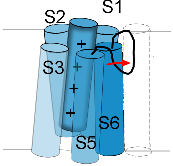
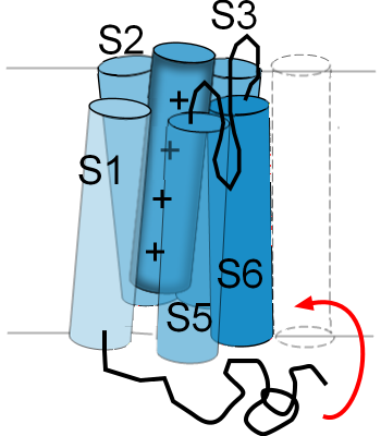 The illustration to the right is an example of how one type of channel inactivates. There is
a twisted black line attached to the cytoplasmic side of S6. This represents
one end of the membrane-embedded protein; it is called the 'N-terminal end'. The curved red arrow shows that,
when the S5-S6 helices are in the 'activated' position ... pulled out of the pore ... the N-terminal end will
move up into the mouth of the pore. As long as the helices are in the 'activated' position this end of the
protein will remain 'latched' in this position where it obstructs the flow of ions through the pore.
The illustration to the right is an example of how one type of channel inactivates. There is
a twisted black line attached to the cytoplasmic side of S6. This represents
one end of the membrane-embedded protein; it is called the 'N-terminal end'. The curved red arrow shows that,
when the S5-S6 helices are in the 'activated' position ... pulled out of the pore ... the N-terminal end will
move up into the mouth of the pore. As long as the helices are in the 'activated' position this end of the
protein will remain 'latched' in this position where it obstructs the flow of ions through the pore.
This type of inactivation gate was the first discovered and has been referred to as a 'ball-and-chain'; the
'ball' is the twisted portion near the end of the 'chain'.
There are other ways in which the inner opening of the pore can be blocked but this is the example most often
used to illustrate this type of gating behavior.
...at the external opening
 The linker between S5 and S6 functions as a selectivity filter and determines which ions can pass through
the pore. Its structure resembles a hairpin loop that hangs part way down into the pore. Accordingly, it is
often referred to as a P-loop.
The linker between S5 and S6 functions as a selectivity filter and determines which ions can pass through
the pore. Its structure resembles a hairpin loop that hangs part way down into the pore. Accordingly, it is
often referred to as a P-loop.
The illustration to the left shows the P-loop stretched out into the opening of the pore as indicated by the
red arrow. The normal position for this loop is shown in the previous illustration. If the P-loop moves in
this manner it will 'collapse' the pore and obstruct the passage of ions. Not all channels have this type of
inactivation gate. Some channels even have inactivation gates at both pore openings.
Last Updated: 9/17/2014
Continue to Activation
Return to home page